
vip@litongglass.com
+86 16632961602

Abstract:This paper introduces the design focus of the planar turning unitized curtain wall system based on the case of the unit curtain wall project of Shenzhen Zhongjin Building, especially the unit system structure, unit system waterproofing, structural connection design, etc., and briefly states the overall force analysis of the keel structure.
Keywords: unit curtain wall; zigzags; inner casement window; Structural analysis
1. Introduction
In the contemporary architecture industry, the building skin introduces more geometric elements such as broken lines, arcs and irregular lines to form a three-dimensional and rhythmic texture skin, which can not only express the different textures of the building, but also make the building present a variety of visual effects. The curtain wall, which forms a plane turning through multiple polygonal lines, is increasingly used in the building skin because of its beautiful shape and strong sense of hierarchy. However, there are certain difficulties in the design and construction of the planar turning curtain wall, especially the planar turning unitary curtain wall, which requires designers to have some in-depth research on the above-mentioned curtain wall design. Combined with the case of the unit curtain wall project of Shenzhen Zhongjin Building, this paper analyzes and summarizes the design of the planar turning unit curtain wall system, which is for the reference of the majority of curtain wall engineering designers.

2. Project overview
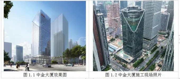
Located in the central area of Houhai in Nanshan, Shenzhen, adjacent to Keyuan Avenue and Haide 3rd Road, CICC Tower is a corporate office headquarters building with a curtain wall area of about 32,500 square meters, and will become a landmark building in the central area of Houhai after completion. The project mainly consists of a 30-storey tower with a height of 153m and a podium of 3 floors with a height of 16.2m. The distribution of curtain wall system mainly includes the standard unit curtain wall of the tower, the cable net curtain wall on the northeast side of the tower, the vertical and horizontal frame curtain wall of the 4-5 floors, the glass rib all-glass curtain wall of the podium, the hyperbolic glass curtain wall of the media tree at the main entrance, and the curtain wall of the podium daylighting roof. (Fig. 1.1~1.2)
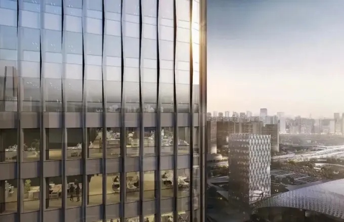
The façade of this project is relatively complex, and the architect's design concept of "big tree" is reflected in all parts of the building, such as the lobby with interlaced light and shadow in the forest, the tower façade like tree bark, the sky lobby with tall trees, and the futuristic media tree.
3. Introduction to the design of unitized curtain wall system
3.1 Composition of the unit
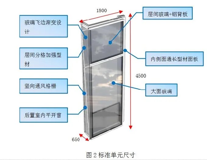
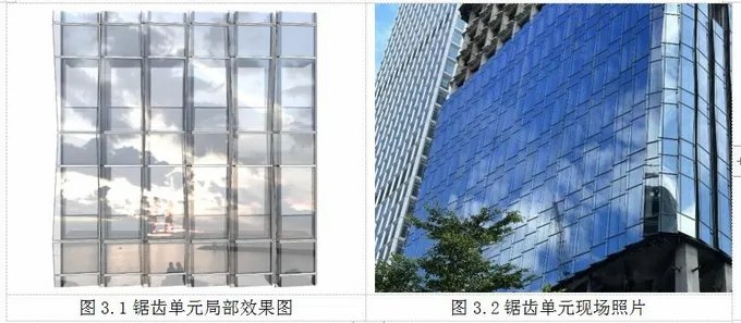
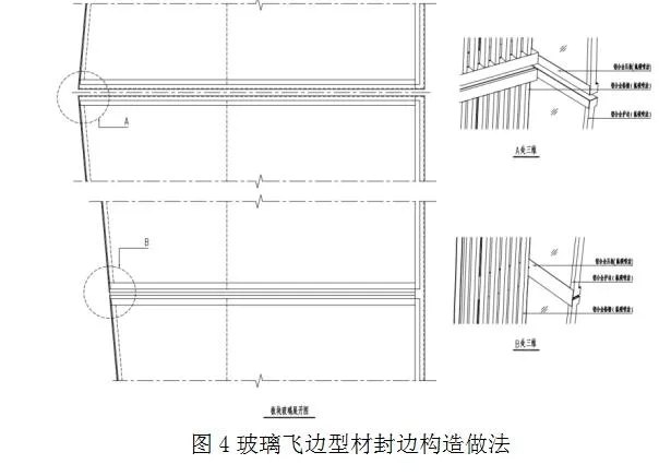
The standard unit plate is 1800 mm (width) x 4500 mm (height), the cross-section is zigzag, the maximum thickness of the plate is 650 mm, and the weight of the plate is about 900 kg (Fig. 2). The façade of the standard unit is divided into 2 pieces of glass by the middle beam, of which the interlayer glass configuration is 8 semi-tempered + 1.52PVB + 8 semi-tempered + 12A + 8 tempered laminated hollow ultra-clear glass, and the large glass configuration is 8 semi-tempered + 1.52PVB + 8 semi-tempered + 12A + 10 tempered laminated hollow ultra-clear glass, and the glass with cantilevered laminated gradient size flash design, the upper and lower left and right plate glass flashes are diagonally opposite, and the overall appearance of the staggered arrangement is beautiful (Fig. 3.1~3.2). The flash glass needs to consider the film removal process, and the side of the glass is covered with a decorative edge banding panel, and the decorative edge banding plate is partially widened at the position of the beam buckle cover to cover the end of the buckle cover, showing a sense of delicacy in the design (Fig. 4).
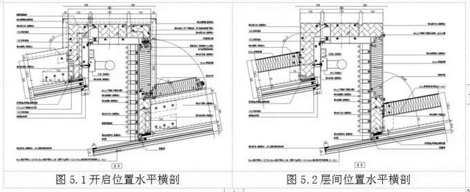
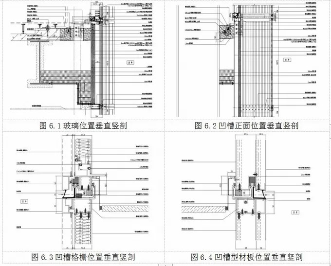
One side of the groove on the side of the zigzag plate is a vertical ventilation grille, and the inner casement window is hidden in the interior side behind the vertical ventilation grille, and the rest of the position is a reinforced profile except for the casement window; On the other side of the groove is an aluminum profile panel with a long trunking to hide the light wiring. The horizontal cross-section node method of the standard element is shown in Figure 5.1~5.2, and the vertical cross-section node method is shown in Figure 6.1~6.4.
3.2 ventilation grille and internal casement window design
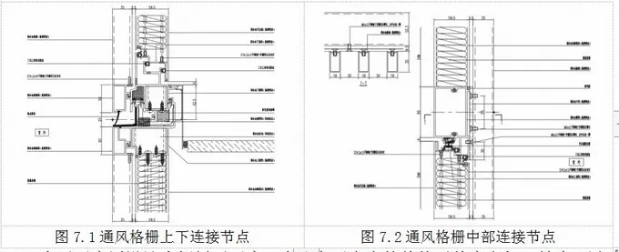
The units are ventilated with concealed casement windows behind the ventilation grille on the grooved side, thus maintaining the integrity and simplicity of the façade. The ventilation grille is 18mm wide rectangular section, the net spacing is 30 vertical arrangement, in order to improve the installation accuracy and quality of the grille, the grille is made into a component form, and then the joint between the inner column and beam is waterproofed, and then it is hung into a hanging, and the position of the middle beam is fixed by the clamp, and at the same time plays the role of anti-tripping (Fig. 7.1~7.2). Adjust the position of the clamp within the opening sash to avoid the normal line of sight of people, and at the same time reduce the height of the clamp, so as to achieve the best balance between the anti-shaking of the grille and the reduction of the impact on the field of vision after the window is opened.
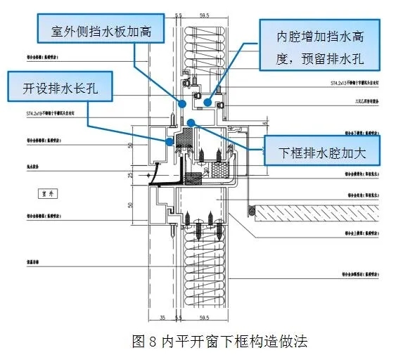
In order to improve the overall flatness and processing accuracy of the opening sash and avoid the color difference of spraying between different substrates in the room, the deepening design is adjusted to the aluminum profile opening fan. The window hardware and handle are all hidden, and the overall design is simple and beautiful. The opening fan is made of composite foam strip with less hardness, and the corner position is made of finished corner adhesive film to ensure flatness and improve waterproof performance. In order to reduce the splicing joints between the window frame and the curtain wall keel, the window frame, the unit beam and the column are all combined into an integral mold, and the height of the outdoor side water baffle at the lower frame position is heightened, the drainage groove cavity at the lower frame position is increased, and the drainage hole is reserved at the hanging position between the lower beam and the grille frame, so as to improve the overall anti-drainage performance of the opening fan system (Fig. 8).
3.3 Unit connection design
1) Anti-side connection design of the unit
The cross-section of the unit body is zigzag, and the overall keel is composed of the male and female columns of the unit, the center column at the corner, and the upper and lower plugging beams and middle beams (Fig. 9). Considering that the main structural plate of the project is also a zigzag design, and the back plate is only set behind the glass panel, if the crossbar diagonal brace is used for design, there will be an exposed diagonal brace and a certain impact on the installation of the on-site plate. In the process of deepening the design of this project, the design scheme of the anti-side reinforced profile was innovatively proposed, the reinforced profile is located in the inter-layer lattice position on the side of the groove, and the full grid is arranged through length, and the strong connection design of the interpenetrating unit mother column and the corner column is carried out, and the reinforced profile is connected with the plate pendant, the overall stiffness is large and the transmission of force is more direct, and the reinforced profile can double as a panel. (Fig. 10.1~10.2)
Considering that the cross-section of the mother column at the groove position is wide, the structure of increasing the diagonal brace plate is adopted in the design of the plate pendant, which strengthens the lateral support of the column at the support position and increases the torsional resistance of the column itself.

2) Unit column beam connection design
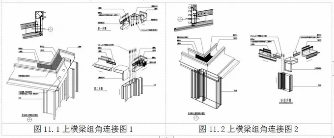
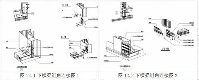
On the one hand, in order to improve the stiffness and stability of the plate connection, ensure that the corner of the sawtooth plate does not form geometric movable, on the other hand, in order to accurately locate and control the accuracy of the angle in the assembly process, the upper and lower beams of the unit plate and the plate column adopt the way of close fitting and connection of the profile group angle, and the screw limit is used between the group angle and the column, and the reliability of the connection of the unit plate itself is guaranteed. It makes the transmission of shear force between the upper and lower plate columns more direct, and can effectively ensure the high precision of plate assembly at different angles. The upper beam and the column group angle connection detail 11.1~11.2, the lower beam and the column group angle connection detail 12.1~12.2.
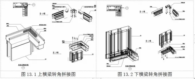
In order to ensure the reliability of the connection position, ensure that the slotted sawtooth plate will not cause water leakage due to joint cracking in the process of processing, assembly and hoisting, and prevent the sawtooth plate from cracking due to the "splitting" phenomenon in the transportation process, the profile ferrule group angle (Fig. 13.1~13.2) is set at the corner splicing position of the beam during the design, and the stainless steel connecting piece is arranged at the bottom of the lower beam and the invisible part of the interior side of the upper beam to be strengthened.
3.4 plate anti-drainage design
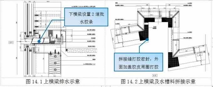
The project has been fully investigated and compared in the process of deepening the design, and the external drainage method is adopted based on the following considerations. First of all, there is a multi-section splicing situation on the cross beam on the unit plate, if the internal drainage is adopted, even if the mortise and tenon glue is played at the joint position, there is a great hidden danger of water leakage because the internal glue quality cannot be visually checked; Secondly, once the tenon glue at the joint of the inner drainage is cracked during transportation or hoisting, it cannot be treated on site because it is located in the inner cavity; Finally, the upper beam is spliced in the shape of "several", with multiple turning and detours, and the internal drainage cannot ensure the smooth drainage.
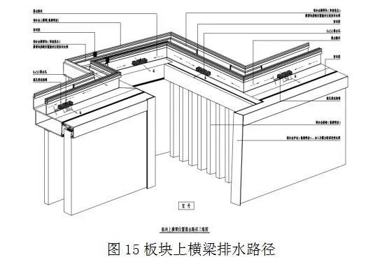
The unit plate adopts an external drainage scheme, which can visually check whether the drainage hole is in place, and at the same time, the drainage is direct, which can ensure smoothness. The waterproof sealing effect at the joint of the upper beam is good, the joint position is glued and sealed first, and the outer side is covered with rubber around the ring, and the two seals are waterproof (Fig. 14.1~14.2). The project uses external drainage, which has been verified by performance testing, and the overall watertightness performance has reached the highest level of 5 in the classification index in the specification [1]. (Fig. 15)
3.5 keel structure analysis and calculation
Name: Litong Glass
Mobile:+86 16632961602
Tel:+86 16632961602
Email:vip@litongglass.com
Add:Shahe city,Hebei,China